


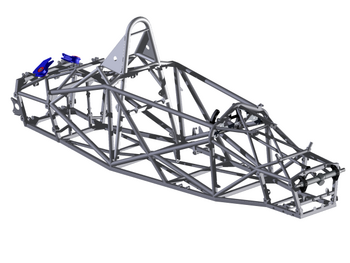
 The picture shows the front of the frame where three seperate parts of the bike meet together and are welded together. This is just above the front fork of the suspension. There would be a considerable amount of load going through this section of the bike. The weld is also very neat which suggests the parts are easily welded together.
 http://www.gtbicycles.com/GTFiles/ProductImages//2000_1300_G10AVA1D_255.jpg
 The material will now be analysed. As alot of the numbers are the same, they have been given equal values for the analysis phase. Each section is worth 9 points and a maximum of 54 can be attained.
 As alot of the data is similar or the same, the results are ranged quite close together. Out of the 9 materials available only 3 would suffice for the application. Aluminium 6061, Aluminium 6063, and Aluminium 7050. The reason for this is their strength is greater than the latter grades of Aluminium, the stronger the material the more resistant it will be to deformation under loads. The material must also be easily worked with, and due to grades above 7000 having poor weldability and corrosion resistant qualities, Aluminium 7050 must be ruled out. This leaves a choice between Aluminium 6061 and Aluminium 6063.
 The material will now be analysed. As alot of the numbers are the same, they have been given equal values for the analysis phase. Each section is worth 9 points and a maximum of 54 can be attained.
 From the table above we can see that there are some quite mixed results. This is due to the different types and grades of steel available. There are alloy steels which are mixed with other materials, and there are varying qualities of steel depending on its purity. Although the materials are very similar in regards to their properties, the two that would be considered for the crane would have to be the Carbon Steel 1023, and Cast Carbon Steel. This is because Carbon Steel has high strength characteristics as well as a low cost factor. In the crane industry alot of cranes are made out of a carbon steel as mentioned in the materials research. However, this is usually for very large cranes which will carry a much heavier load than compared to the crane we are designing. With this in mind we must consider the weight factor of steel compared to Aluminium. The weight of Aluminium is a considerable amount less than the weight of Steel. This can be seen from the Density of both materials. The more Dense the material the more it weights. For a crane that will need to be carried over rough terrain by people, the lighter and easier it is to transport, the better.
To find the counter balancing weight required for the crane beam to lift 1500kg and the total force going through to the boom, we use moments -
Equate the clockwise and anticlockwise moments:
(About C clockwise) - Xg x 1 = 55.2g x (1.5 - 1) + 1000g x 2
Xg = 27.6g + 2000g = 2027.6Kg mass required for balance
2027.6 x 9.8 = 19870.48N force required for balance
Equating the forces in a vertical direction:
R = Xg + 55.2g + 1000g = 2027.6g + 55.2g + 1000g = 3082.8Kg Mass
4582.8 x 9.8 = 30211.44N Force - Both of which is the total amount acting through to the boom.

Finding the area of the circular support –
Π x [(140-120)/2]2 = 314mm2 = 0.314m2
Therefore the stress acting on the surface area of the circular support is (Using s = F/A)
s = 30211.44/0.314 = 96214.78Nm-2
As there are four supporting strut ‘legs’, the total force would be equally distributed along them as such:
30211.44/4 = 7552.86N per ‘leg’

a = 7552.86 x cos30 = 6540.96N
b = 7552.86 x cos60 = 3776.43N
c = 7552.86 x cos60 = 3776.43NThe second boom/box support has the combined forces of the previous boom/box supports weight as well as the total weight of the boom with maximum load and counterweight.

Using previously done calculations of structure weight –

Therefore, the approximate mass of the boom support can be assumed to be ~ 27.6kg = 270.48N
So the total force acting down on the second boom support is 270.48 + 30211.44 = 30481.92N

Overall force acting downwards on the structure is – 52.5 + 27.6 + 27.6 + (13.4x4) = 161.3kg
Which is 1580.74N of force, as well as the force of the weight and counterweights which gives
9800 + 19870.48 + 1580.74N = 31251.22N

