Welcome to The ME2045 Group J Crane Project Blog page!


This entire site is to give a guide to Group J`s efforts to design a small portable crane for use in disaster relief before our final submission of work and our presentation.

Following our first meeting (See the Minute Meetings Topic for reference) the following positions have been allocated;

D.Scriven Project Manager
R.Sidhu Chief Designer
H.Singh Sall Finnance Officer
J.Sidhu Materials Specialist
R.Shukla Stress Analysis

For Our Progress up to date please see the Project Plan below and then head to the relevant topic and we hope you find our work interesting!

Showing posts with label Rajinder Sidhu. Show all posts

Sunday, 2 May 2010

Summary

Project Summary

As a group we feel the project has been successful. If we were to carry out the same task again, we all agree that we would do nothing different. The crane itself was designed and tested very well. The group had a very wide variety of skills, the design engineers were very confident with CAD, and the mechanical engineers were very confident with the stress analysis. As a group we worked very well together from the beginning stages to the very end of the project. We set deadlines and met them almost perfectly every week, and with sometimes up to three meetings a week we were getting through the work at a very good rate. We as a group feel we could not have had a better group to work with.

During the duration of the project we faced some challenges. The hardest were probably the choice of material and the stress analysis. We had to change material a few times after stress analysis so the crane itself would not fail under stress. The choice of the design was also a difficult phase, we had a lot of different designs and different crane styles to choose from. Choosing the right one was a vital stage in the development of our crane, a bad choice would ultimately have led to a bad project.

Our final design was a very good design and we felt it was the best it could be, it was engineered to a safety factor of 1.5 and very different to most the other designs we saw. We felt a lot of the designs we saw had many more flaws than our own.

To summarise, the group was very happy with the whole project and the final design. We all feel that given the chance again we would not change anything and would carry out the task in the same way.

Wednesday, 28 April 2010

Calculations For Buckling

Shown below are the calculations carried out to find out if the crane stucture would buckle and fail. The calculations were carried out on the members which would be likely to buckle under a compressive load.


The calculations prove that the members under compressive load would not buckle at 1.5 times the recommended lifting capacity.

Thursday, 22 April 2010

Final Design - CAD Model

The images below show the final design of the portable crane.


Finite Element Analysis of Final Design

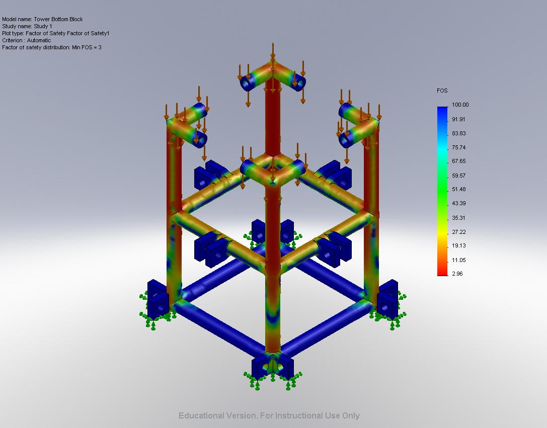
Shown below are images of the studies carried out on the final design CAD model. The following plots were created, so that we as a group could get an idea of how the crane would behave, when the load is applied. Each component of the crane was tested seperately. The axle, boom, legs, tower bottom block and the tower top block were tested. The plots created from left to right were displacement, factor of safety, strain and stress.

Axle
Material - Alloy Steel


Boom
Material - Alloy Steel


Leg
Material - Aluminium 6061 Alloy


Tower Bottom Block
Material - Aluminium 6061 Alloy


Tower Top Block
Material - Aluminium 6061 Alloy


The displacement plot shows us where the component would dimensionally change the most. All five of these displacement plots show that the dimensional change is within a tolerable region.

The Factor Of Saftey plot shows us whether the component is capable of carrying more load. All five of these plots show that the level of safety is within acceptable regions.

The strain plot shows us how the component would physically change under load. All five of these strain plots show that the physical change is within a tolerable region.

The stress plot shows us where on the componet the most stresses occur. All five of these stress plots show that the stress is within a tolerable region. This is because the stress does not go beyond the yield strength of the material.

Finite Element Analysis - Crane Boom Error

By carrying out a study on the crane boom we have found out that the structure is not rigid and strong enough to lift the load without plastically deforming. The image below shows how much the boom would deform when loaded.


The red arrow on the scale indicates the yield strength of the material, in this case aluminium 6061 alloy. Every stress above this arrow would plastically deform the component. In the case of this boom, the failure point would in the green and red areas. To prevent this the structure was further developed so that it became more rigid. The material was also changed to alloy steel. This material was chosen because it has a higher value yield stress and a higher Young's modulus. The image below shows how these changes made a significant improvement on the component.


The red arrow not being on the scale, indicates that the stresses do not reach the yield strength of the material and therefore does not plastically deform.

Thursday, 8 April 2010

Individual Design CAD model - Rajinder Sidhu

The following images show the proposed design of the crane model in SolidWorks.


There are four main components that make up the design of the crane. These are the legs, base box, middle box and the crane boom. The pulley system is located within the crane boom. Trusses are used in the structure to make the frame rigid. The frame would be made from square and tubular steel or aluminium piping.

Wednesday, 7 April 2010

Bearing Research - Finite Element Analysis

SolidWorks was used to create these studies which tell us how the bearings would behave under load. Three different types of bearing where studied and the most appropriate was chosen for our final group design. The three types of bearing studied were the roller, thrust and ball type of bearings. The force applied to the bearings was 490 N. This is because the force from the load being lifted would be divided between many bearing in the race.

Roller Bearing


Axial loading - 490 N

Top view Bottom view

Radial loading - 490 N

Top view Bottom view

This type of bearing has a low axial load capacity and high friction under axial loads.However, it has a high radial load capacity. This study also shows that the stresses exerted onto the bearing do not exceed the yield strength of the material (chromium stainless steel alloy).This means the bearings used on our design will not plastically deform under load.

Thrust Bearing

Axial loading - 490 N

Top view Bottom view

Radial loading - 490 N

Top view Bottom view

This type of bearing has a high axial load capacity but a lower radial load capacity. This study also shows that the stresses exerted onto the bearing do not exceed the yield strength of the material (chromium stainless steel alloy).This means the bearings used on our design will not plastically deform under load.

Ball Bearing

Axial loading - 490 N

Top view Bottom view

Radial loading - 490 N

Top view Bottom view

This type of bearing has a high axial load capacity and a high radial load capacity. This study also shows that the stresses exerted onto the bearing do not exceed the yield strength of the material (chromium stainless steel alloy).This means the bearings used on our design will not plastically deform under load.

From doing these studies we can see that the ball type of bearing would be the most suitable for use in our crane. This is because the ball type of bearing can handle axial and radial forces and also moments very well.