Thursday, 22 April 2010
Finite Element Analysis of Final Design
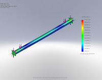
Axle
Material - Alloy Steel


Boom
Material - Alloy Steel


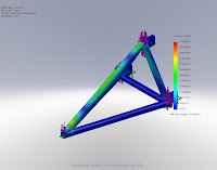
Leg
Material - Aluminium 6061 Alloy


Tower Bottom Block
Material - Aluminium 6061 Alloy


Tower Top Block
Material - Aluminium 6061 Alloy


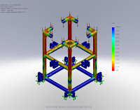
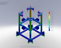
The displacement plot shows us where the component would dimensionally change the most. All five of these displacement plots show that the dimensional change is within a tolerable region.
The Factor Of Saftey plot shows us whether the component is capable of carrying more load. All five of these plots show that the level of safety is within acceptable regions.
The strain plot shows us how the component would physically change under load. All five of these strain plots show that the physical change is within a tolerable region.
The stress plot shows us where on the componet the most stresses occur. All five of these stress plots show that the stress is within a tolerable region. This is because the stress does not go beyond the yield strength of the material.
Finite Element Analysis - Crane Boom Error

The red arrow on the scale indicates the yield strength of the material, in this case aluminium 6061 alloy. Every stress above this arrow would plastically deform the component. In the case of this boom, the failure point would in the green and red areas. To prevent this the structure was further developed so that it became more rigid. The material was also changed to alloy steel. This material was chosen because it has a higher value yield stress and a higher Young's modulus. The image below shows how these changes made a significant improvement on the component.

The red arrow not being on the scale, indicates that the stresses do not reach the yield strength of the material and therefore does not plastically deform.
Wednesday, 21 April 2010
Material Anaylsis

1 Aluminium 6061 is a commonly used grade, hence why it is used for the comparison.
2 VCB-20 is a commonly used grade of carbon fibre found in the automotive industry, hence why it is used for the comparison.
3 Carbon fibre does not actually have a yield strength. It will always elastically deform in accordance with hookes law until its ultimate tensile strength (UTS). Once it reaches its UTS it will fail.
4 Grade 5 (Ti6-4) is a commonly used titanium alloy, found in many industry applications, hence why it is used for the comparison.
Evaluation of Materials
As there are 12 materials, a scoring system ranging from 1-12 will be used, 1 for the worst material and 12 for the best material in a given field.

The table clearly distinguishes the differences between each material, however cost is a more dominating factor and will have more of an influence over the decision of which material is chosen. This is to be discussed between the group and from then we will analyse and choose the final material.


